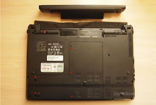
Step 1
Removing the memory cover
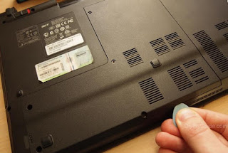
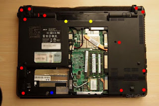
The procedure is very simple. Just unscrew the five screws and then use a plectrum to force the edges of the laptop to remove the cover.
I recommend that you keep the screws in the position where you found them to be sure not to miss to position them during reassembly. In any case, I have marked with different colors with the different screws that you will encounter.
Step 2
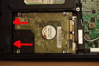
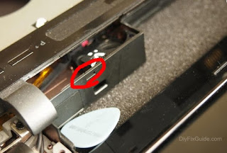
Removing hard drive
In order to replace the hard disk, you have to unscrew the two screws that I have marked in the picture below.
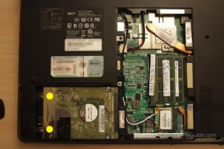
Once this is done, you can pull off the clear plastic tab on the metal piece.
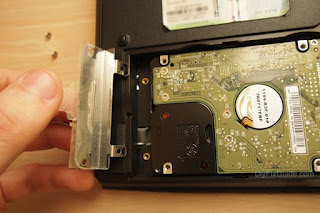
The hard drive will be free to come off after pushing it to the left (and therefore disconnected from its connector SATA)
Step 3
< br />
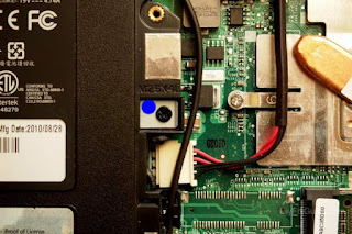
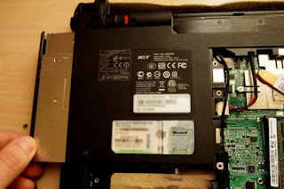
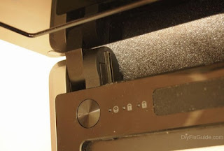
Removing the optical drive
Just unscrew one screw and pull outward.
Step 4
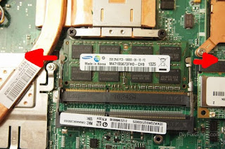
Removing the RAM
Ram modules are held in place by two metal side rails. You have to push them to the outside to make sure that the module may be lifted by only with the possibility to remove it.
Step 5
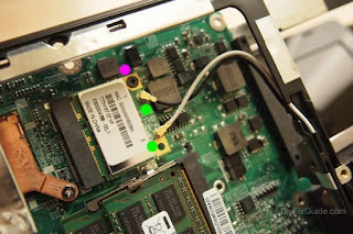
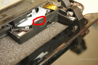
Removing wireless card
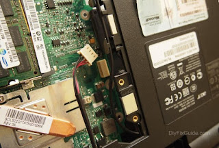
The wireless card is located near the RAM module. You have to unscrew one screw and remove the cables of the two antennas.
Step 6
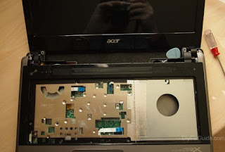
Removing the keyboard
Unscrew all the screws are located under the laptop. As usual, I marked with different colors with the different types of screws.
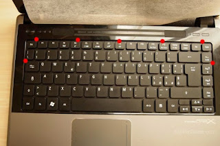
On the other hand, we have to remove the keyboard. Looking closely you can see small pieces of plastics. They are still going towards the outside to make sure to unlock the keyboard. I have marked their position in the picture below.
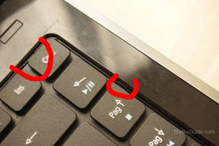
Here’s how they look seen up close.
Warning: when you pull the keyboard towards you do not crush the ribbon cable that connects to the motherboard (you could ruin the keyboard and the motherboard connector).
There is a need to raise the black lever of the connector to pull out the ribbon cable of the keyboard.
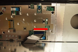
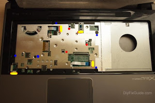
At this point, you have to unscrew all other screws that were hidden by the keyboard. In addition you have to disconnect all the cables from their connectors flat.
Special connectors to the free position to release the cables
And here’s a snap connector and its cable head thrus t out.
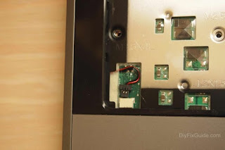
That’s left to do now is insert a shim between the top cover and the bottom cover of the laptop. I used the usual guitar pick.
There are joints to push that I’ve marked in the photos below.
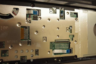
I also put a photo of the view from the rear top cover should you need to replace the power on or output optical drive and one with all the screws ordered.

Step 7
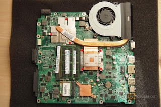
Removing the Motherboard
The motherboard is held in place by only two screws.
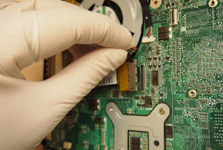
But first you need to disconnect the cables from their connectors.
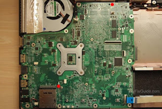

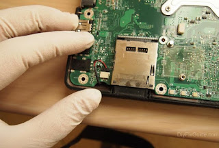
At this point the motherb oard is off quite easily by lifting it from the right side.
Step 8
Removing the CPU
The CPU and GPU share the same heat sink. So we will have to unscrew all the screws that hold it firmly attached to both.

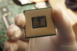
In order to remove the CPU (for a possible upgrade to intel i5 or i7), you must now turn counter-clockwise the black screw that is located on the socket.
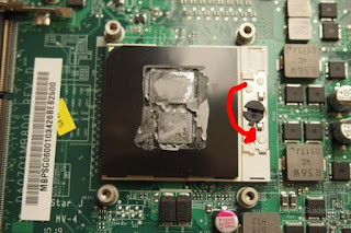
At this point, you can remove the CPU.
No comments:
Post a Comment